
A Forest and Bird Warkworth Project
Wiring Information
Clicking on the pdf document, you will see the wiring instructions for ScanACat that match the software available on GitHub.
This includes a FET and control terminal block that is not required currently. These are there for future development and testing.
Since developing this, there are some alternatives relative to the mkr series boards, that could make assembly easier such as the screw terminal block breakout module.
Wiring Information:
General Notes On Assembly
The type of housing one may desire to use will greatly depend on application.
Special Note: Use shielded cables between Arduino Enclosure and RFID/ IR Breakbeam enclosure, and RFID TX/RX. I suggest also using shielded cable to the IR break beam components. Shielded cables should be grounded, to the ground from your power source.
In our case we chose a fairly heavy duty storage bin, and cut an entry and exit hole for animals to enter and leave.
Some of the items used were just things laying around the garage from prior projects, so were chosen simply based on it being something that could be used to achieve the job, without purchasing anything additional.
There is more information below on some of what we chose to do when implementing the prototype.
Below is a trailcam photo of ScanACat deployed on a beach (an old jute coffee bean bag was partially glued to the storage box so that it was less obvious.


Arduino Module, aluminium box with part cut out for wifi signal.
Powerbank
RFID Module & voltage regulator
for IR Break Beams; both enclosures are grounded to power bank ground.
Tray for ease of use
IR Break Beam (one at each entry)
RFID Module and Antenna
Antenna design is a discipline I did not want to delve into for this project. As such I bought an RFID module that already had the antenna attached and in an enclosure to hold the antenna shape. Below you can see how the RFID module arrived:

For ease of the project, and not wanting to mess around with antennas, I removed the module from the centre of the enclosure (leaving antenna attached, and then removed the central part of the enclosure so that an animal could walk through it.


The centre was removed from the casing the RFID module came with (leaving the antenna channel).
The aluminium bars on the sides were a convenient way to keep the IR breakbeam transmitters and receivers aligned, and we just tucked the wires for them inside.
The boxes are sitting on a bit of aluminum L bracket and a bit of plastic we had laying around to make a shelf. The antenna enclosure is attached to it as well.
The antenna enters the rfid enclosure with a grommet to protect, as the enclosure is grounded..
There is a pushbutton on the end of the box, for a user to start the wifi-access point. Not pictured, but on the side near the button is a status LED.
There are some holes drilled in the side and floor of the box down low to let any water that might get in out. Also to be able to use tent pegs to secure the box somewhat.
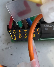
A look inside the RFID Module Box

Header For RFID Module
A look inside the Arduino Box

Originally I used an Arduino SD shield and add the RTC to the proto area of the SD shield, which somewhat reduced wiring needs, but found it really difficult to get to the RTC battery or the SD card using those. So I changed to an SD module that could be installed at right angles (the SD card is up the top and vertically placed), and the same with the Real Time Clock. It was for convenience and ease of use in the long term.
I have an aluminium plate that is grounded (not shown in picture) to the power source ground (all ground wires are).
The terminal blocks also make it easier to connect/disconnect from the connectors if needed.